


 Click here to watch Nyan Sat live!
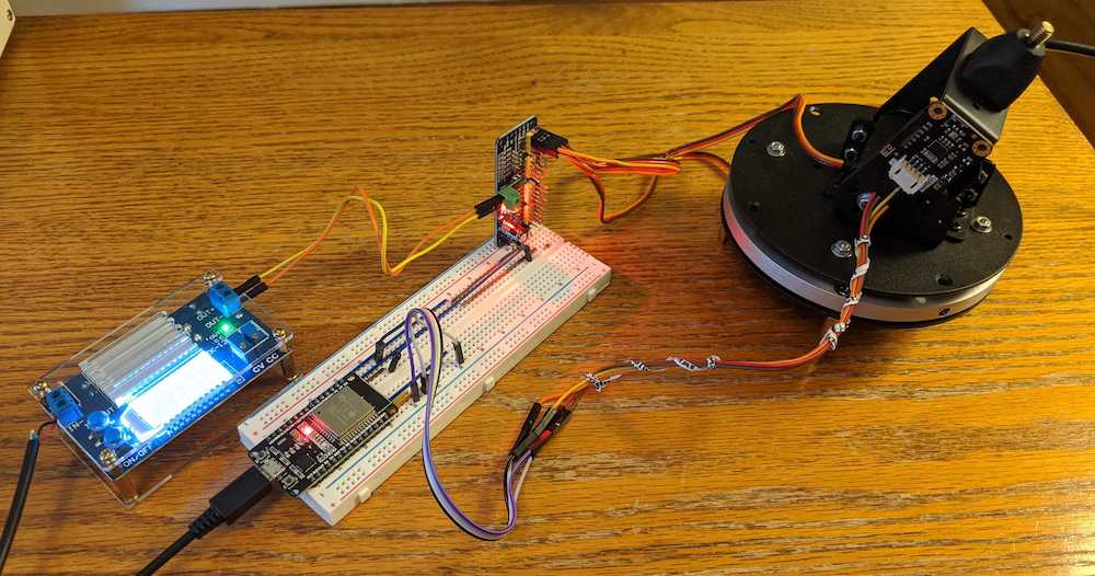
NyanSat Ground Station - What You'll Need
2 axis motor base
The antenna need two degrees of freedom to track satellites: Azimuth (left or right movement, expressed as degrees off true north) and Elevation (up or down movement expressed as degrees up from the horizon). The base has two servomotors that control the position of the antenna, one for each of these degrees of freedom. The motor below the base controls the azimuth, the motor on top of the base controls the elevation.
Inertial Measurement Unit (IMU)
The IMU provides orientation data for the antenna. While the position of the antenna can be controlled by setting positions for the servo motors to move towards, the IMU provides a more accurate & precise data. These instructions assume you are using a B NO055 IMU.
ESP32
This is the microcontroller that contains NyanSat code. It controls the motor driver, collects IMU data, and provides an interface for the user to interact with the base station.
Motor Driver
This component takes commands from the ESP32 and provides the correct PWM signals to the servo motors on the motor base to achieve the desired antenna orientation. The motor driver also powers the motors with independent power rails; this minimizes the risk of brownouts on the control circuitry. These instructions assume you are using a PCA9685 16-channel Servo Driver.
OLED Screen
This is a simple screen that displays telemetry and other data at a glance
Assembling and setting up the Hardware
Setting up the Motor Assembly - Wiring the Motor Driver
The ESP32 connects to the Motor Driver, IMU, and OLED screen via the I2C bus protocol. You will need to set up a daisy-chained clock line (SCL) and data line (SDA) connecting the ESP32 to the three components. By default Pin 21 on the ESP32 is the clock line and Pin 22 is the data line. Start by connecting the lines from the ESP32 to the motor driver's SCL and SDA pins.
While wiring the motor driver and other devices on the I2C bus, make sure to connect their ground pins to the same ground that the ESP32 is connected to. An improperly grounded I2C bus is usually the cause of a no device being detected error, so this is one of the first things to look out for when debugging later on. For power, you will want to use two separate power sources for control and motor power the control electronics become susceptible to brownouts and unreliable behavior if the power rails are shared. In this case, connect the control power to the Vcc pin on the motor driver and the other I2C peripherals, and connect the motor power to the V+ pin on the motor driver.
When connecting the motor pins to the driver board, take note of which motor controls which orientation. The code assume the elevation motor will be connected to channel 0, and the azimuth motor will be connected to channel 1.
To power the motor driver, any reasonable 5V source should work. If you don't have a 5V power supply or battery handy you can even strip a USB cable and connect the 5V and GND wires to the positive and negative terminals respectively.
Connecting the Telemetry Equipment - Wiring the IMU & OLED Screen
Just like the motor driver, the IMU and OLED screen are connected to the ESP32 via I2C. Like before, make sure the ground pins of each device are connected directly to the ground rail that the ESP32 uses, otherwise you might not detect your devices. Power is the same story, connect each device's power pin to the control power rail. For the OLED screen, Pin 12 is SCL and Pin 13 is SDA. The IMU has Pin 23 for SCL and Pin 18 for SDA.
The IMU is slightly more interesting in that there are significantly more ways to get hung up with this component.
The BNO055 IMU usually comes in a small PCB with conductive through hole pins for the connections. When mounting the BNO's PCB, if the pins are not covered with an insulator the device will simply not work when mated to a conductive metal surface. Always tape over exposed pins before fixing any electronic device onto bare metal. Better yet, use an insulating backing, such as a plastic sheet or a wooden bas relief depicting heroic radio operators.
When mounting the IMU, be careful to align the axes with the device correctly. Usually, the PCBs for the BNO055 have a diagram showing the "x, y, z" coordinates that the BNO055 is expected to align to. While mounting the IMU keep two axes parallel to the plane of the mounting surface, with the remaining axis perpendicular. This makes the coordinate system much easier to visualize and work with..
Getting the ESP32 Ready - Installing MicroPython
To run NyanSat code on the ESP32, you will need to flash it with MicroPython firmware first. PyPI has a package called esptool that makes it easy to flash your ESP32 from your computer. You can install it using pip, much in the same way as one installs other packages. Once esptool is installed, you need to erase before the ESP32 is ready to run python. To get started, erase any pre-existing firmware by running the command run esptool.py --port <your ESP's serial port> --chip esp32 erase_flash from you computer. Then, go to the Micropython project's download page and get the esp32 Micropython firmware. Press and hold the "BOOT" button on the ESP32 for a few seconds, to reduce the chances of a "Timed out waiting for packet header" error (You can omit this step safely, but our experience says not to). Finally, to flash the firmware run the command esptool.py --port <your ESP's serial port> --chip esp32 write_flash -z 0x1000 <your downloaded firmware file>. Now your ESP32 should be ready to run python code directly!
Loading the software
For instructions on how to install NyanSat on your ESP32 and the interactive shell that interfaces with it, checkout out GitHub repo at https://github.com/RedBalloonShenanigans/antenny.
Using the antenna
Once you have the software installed on your host machine and the ESP32, you can start playing around with it! Once you are in the shell, type elevation <angle> or azimuth <angle> to move the antenna where you want it to go. You can also see the system's state using the shell's telemetry interface, or also take a look at some of the features NyanShell provides you for your hardware!
Now you have a fully functioning satellite receiving station! Go to a site like in-the-sky.org to see what's overhead, pick a satellite, put in the orbital parameters, and see what your chosen object is transmitting.
Gotchas
As with any project, you may come across a few snags in the road—we certainly did! Here's a few that we encountered and how we solved them. As a general rule, when you try to debug:
- Use the command
python3 -m nyansat.host.shellto interact with your device; this exposes only the shell to you - Reset the device by pressing the
BOOT/ENABLEbutton on your ESP32, or pressingControl + Dwhen using thereplinterface
After a NyanSat install, the device reports "no module named 'logging'"
This usually occurs after a reinstall and appears to be an issue with upip, the MicroPython equivalent of PyPI. If you come across this issue, enter the command repl in nyanshell and type the following commands:
>>> import upip
>>> upip.install('logging')
This will install the logging module again. You can verify that it is installed by checking the lib directory on your base station.
NyanSat stuck in SAFE MODE
SAFE MODE is a last resort for your NyanSat when it cannot properly initialize your motor driver. In this mode, it initializes a software mock motor system so you can at least play around with the interface. This is useful for debugging and developing features, but can be a pain when you're trying to use the base station! Your NyanSat might be in SAFE MODE for several reasons:
- Your physical pin configuration may not match up with what NyanSat is using: To verify this, run
configsto list out the parameters your NyanSat is using. If you see a mismatch for your motor driver's I2C pinout, you can change the configuration parameter using thesetcommand. Take a look at the section for "Devices are not detected" for a more thorough discussion. - Your motors' I2C address may not match up with what NyanSat is using: To verify this, run
configsto list out the parameters your NyanSat is using. Then, usei2ctestorpwmtestto verify which address your motor driver is using; if you see multiple addresses, the first one is usually correct. If you see a mismatch, you can change the configuration parameter by using thesetcommand. - Your motor driver is not at PCA9685: To verify this, run
pwmtest. IfPWM connection established?isFalse, but the other values areTrue, you may have a different motor driver. Fear not!AntKontrol's API is designed to be extended, so you can create a new motor implementation for your unique motor driver! If you choose to do so, make sure to submit a Pull Request on the main Antenny Project Repo. - Your motor driver is broken! To verify this, first make sure the cause isn't any of the ones listed above. If
i2ctestorpwmtestdon't return any address and you are sure your wiring is correct, you might have a defective motor driver :( Unfortunately, you need to replace your motor driver to move your base station.
Devices are not detected
Assuming your devices are not defective, this could happen if your software or physical pin configurations are not correct. The first thing to do is verify the software pin configurations by running the configs command. If any pins are misconfigured in your software configuration, you can use the set command to fix it.
It is also possible that your physical pin configurations are not correct. Here are some possible pin misconfigurations:
- SDA & SCL are switched
- Logical GND pins are not all shared (connected to the same place)
- Logical Power supply is not outputting the minimum voltage (3.3-5V usually)
- Logical Power supply is shared with Motor Power supply (VERY bad practice)
Try to go through your physical configuration and ensure you're using the best practices to connect everything:
- If you have exposed pads that directly contact metal, cover it with an insulator
- Make sure your soldering job actually makes a connection
- Ensure distinct power rails for logic and motors
- Be organized with your wiring
- Leave some slack in your wiring so there's not significant stress on the connections
- Secure connections that can potentially come loose
I2C Addresses seem to change
I2C devices use addresses to know how to communicate with each other. Some devices allow you to change the address physically by breaking out the pins responsible. If these pins are not connected to anything, it is possible that their voltage is undefined, or "floating". This results in the device configuring itself with unexpected addresses from run to run. To ensure a stable I2C address, make sure each address pin has a defined voltage value. This is usually done by tying each pin to ground, but consult your device's data sheet to properly handle this scenario.
NEXT CHAPTER